Overview
The kinematics/dynamics model of an articulated robot is the primary input of RobCoGen. The format of robot models is text with a simple syntax tailored for the domain. The language is called Kinematics-DSL (DSL stands for Domain Specific Language), and it is documented in this page.
The logical structure of a file ("document", or "model") is the following:
Robot <name>

  <link 0 spec> // the robot base
  <link 1 spec>
  //...
  <link n spec>

  <joint 1 spec>
  //...
  <joint n spec>
Any link block contains an id, the inertia properties, and a possibly empty
list of children links. The geometrical constants of the robot are encoded in
the joint parameters, which are extensively explained below.
The format allows to model any kinematic tree, that is a mechanism where each rigid body has one and only one parent (except the base), but can have multiple children.
Example
Here is the sample robot model file included in the distribution of RobCoGen:
Robot Fancy
{
/*
 * A fictitious kinematic chain, without branches.
 * All the links are hollow cylinders infinitely thin (internal and
 * external radii are the same) with radius equal to 0.05 meters,
 * unit length, unit mass.
 * They are connected by five joints: revolute, prismatic, revolute,
 * prismatic, revolute.
*/

RobotBase base0 {
    inertia_properties {
        mass = 1.0
        CoM = (0.0, 0.0, 0.0)
        Iy=0.0  Ix=0.0  Ixy=0.0 Iz=0.0  Ixz=0.0 Iyz=0.0
    }
    children {
        link1 via jA
    }
}

link link1 {
    id = 1
    inertia_properties {
        mass = 1.0
        CoM = (0.5, .0, .0)
        Ix=0.0025  Iy=0.33458  Iz=0.33458  Ixy=0.0  Ixz=0.0  Iyz=0.0
    }
    children {
        link2 via jB
    }
}

link link2 {
    id = 2
    inertia_properties {
        mass = 1.0
        CoM = (0.0, 0.0, 0.5)
        Ix=0.33458  Iy=0.33458  Iz=0.0025  Ixy=0.0  Ixz=0.0  Iyz=0.0
    }
    children {
        link3 via jC
    }
}

link link3 {
    id = 3
    inertia_properties {
        mass = 1.0
        CoM = (0.5, .0, .0)
        Ix=0.0025  Iy=0.33458  Iz=0.33458  Ixy=0.0  Ixz=0.0  Iyz=0.0
    }
    children {
        link4 via jD
    }
}

link link4 {
    id = 4
    inertia_properties {
        mass = 1.0
        CoM = (0.0, 0.0, 0.5)
        Ix=0.33458  Iy=0.33458  Iz=0.0025  Ixy=0.0  Ixz=0.0  Iyz=0.0
    }
    children {
        link5 via jE
    }
}

link link5 {
    id = 5
    inertia_properties {
        mass = 1.0
        CoM = (0.5, .0, .0)
        Ix=0.0025  Iy=0.33458  Iz=0.33458  Ixy=0.0  Ixz=0.0  Iyz=0.0
    }
    children {}
    frames {
       ee {
           translation = (1.0, 0.0, 0.0)
           rotation    = (0.0, 0.0, 0.0)
       }
    }
}


r_joint jA {
    ref_frame {
        translation = (0.0, 0.0, 0.0)
        rotation = (0.0, 0.0, 0.0)
    }
}

p_joint jB {
    ref_frame {
        translation = (1.0, 0.0, 0.0)
        rotation = (-PI/2.0, 0.0, 0.0)
    }
}

r_joint jC {
    ref_frame {
        translation = (0.0, 0.0, 1.0)
        rotation = (0.0, 0.0, 0.0)
    }
}

p_joint jD {
    ref_frame {
        translation = (1.0, 0.0, 0.0)
        rotation = (PI/2.0, 0.0, 0.0)
    }
}

r_joint jE {
    ref_frame {
        translation = (0.0, 0.0, 1.0)
        rotation = (0.0, 0.0, 0.0)
    }
}


}
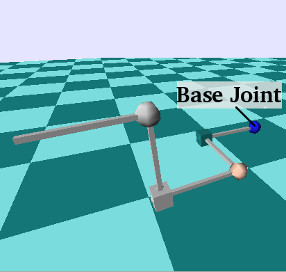
Here is an illustration of the same robot, Fancy, taken from a simulation using RobCoGen-generated code. Spheres represent revolute joints, cubes prismatic ones.
Geometry
This section walks you through the procedure required to model an articulated mechanism with the Kinematics-DSL. It explains how to place the coordinate frames and how to measure lengths and angles. The convention about the placement of reference frames (or "coordinate frames") is definitely the aspect that can be most confusing, and that is typically not documented enough. I tried to avoid such a mistake.
First, the definition of some of the terms use in the text:
-
A kinematic-pair is a pair of links connected by a joint
-
The links of a pair, in relation with the joint, are called predecessor and successor.
-
The links of a pair, in relation with each other, are called parent and child.
-
We say that a parent/predecessor/joint supports the child/joint/successor; the opposite relation is supported by.
Basic modeling
The following applies to kinematic trees (no loops), with one-dof joints only.
1. Ordering. Set the topological ordering for the kinematic tree of your robot: which link is the base, which are the parents/children, etc. This choice induces a total ordering with respect to the relation supports/supported by.
2. Zero configuration. Choose the configuration of the robot you wish to identify with the zero joint-status vector; consider the robot assembled, but neglect joint limits. That is, the zero configuration must comply with the holonomic constraints of the real joints, but it need not respect the range of motion; it might very well be unreachable by the actual robot.1 (Note that no reference frame was mentioned yet.)
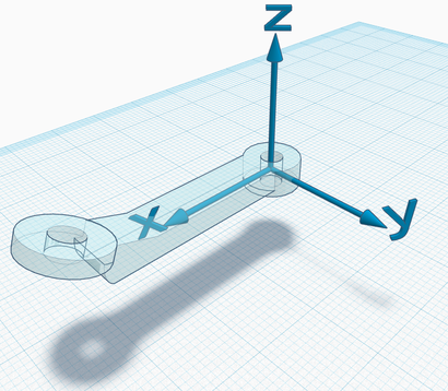
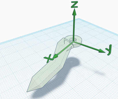
3. Link-frames. Consider each individual link (in isolation), and attach a Cartesian frame to it. The Z axis must lie along the axis of the supporting joint (e.g. the Z axis of a forearm is the elbow axis), but you are otherwise free to choose the pose.2 The link-frame of the base link of the robot can be placed anywhere.
More
The link-frame is the reference used for any quantity related to the link itself (e.g. the center of mass, the pose of other attached frames, the location of the joint axis, etc.).4. Joint-frames. Consider the robot assembled, freezed in the zero configuration. For each joint of the robot, attach a new frame onto its predecessor, in the same pose of the frame of its successor (i.e. the two frames coincide). This is the joint-frame.
5. Geometrical properties.
The pose of any joint-frame relative to the predecessor-frame is
a geometrical constant of the robot. This pose is represented in the
joint sections of a Kinematics-DSL model.
Example
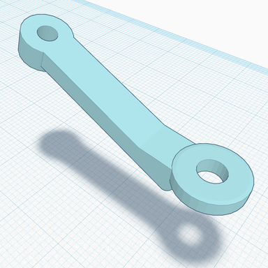
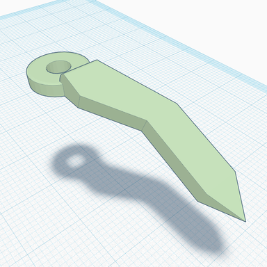
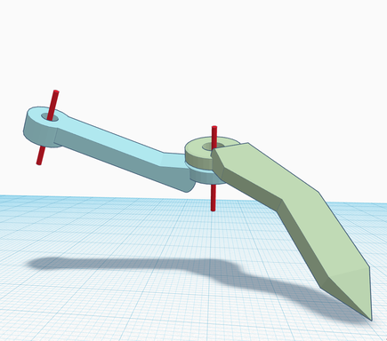
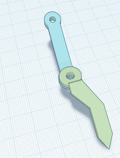
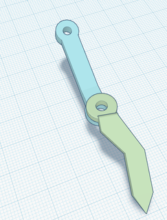
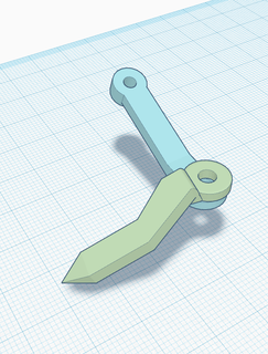
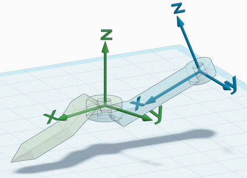
Let's consider a simple kinematic pair, as the extension to a general tree would simply require to reiterate the same steps. These screenshots show the links and the ideal joint axes (in red):
The corresponding section of a model would look like this:
// ...

link Blue {
    id = <i>
    inertia_properties {
        // ...
    }
    children {
        Green via TheJoint
    }
}

link Green {
    id = <i+1>
    inertia_properties {
        // ...
    }
    children { }
}

r_joint TheJoint { // 'r_' stands for revolute
    ref_frame {
        // ...
    }
}
1. Ordering. We choose the blue link to be the parent (and therefore the predecessor of the joint).
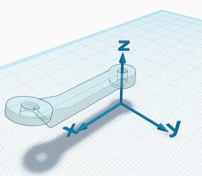
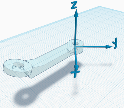
2. Zero configuration. Here are some possibilities:
The choice of the zero configuration is entirely arbitrary, pick an intuitive one in the context of your application.
3. Link-frames. In the examples below, note that the Z axis always lies on the joint axis, but the frame is otherwise free to "move".
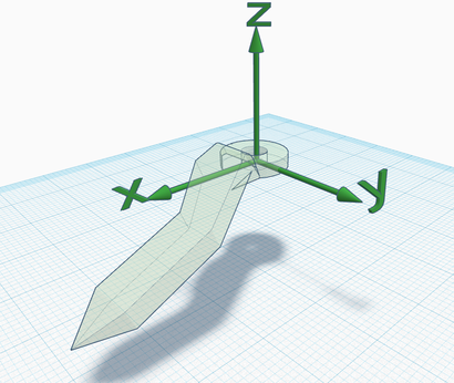
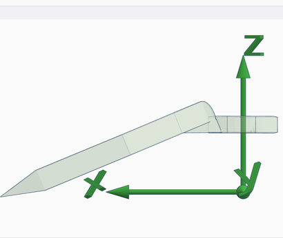
The Z axis could also be pointing in the opposite versus; the right hand rule on the Z axis determines the direction of rotation which corresponds to an increase/decrease of the joint status (choose the versus of Z to fix the preferred convention). Also, note that all combinations between the previous and these screenshots are possible, i.e., the choice of the zero configuration is independent of the choice of link frames.
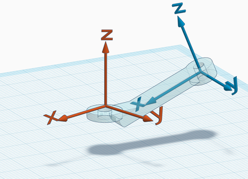
4. Joint frames. At this point, the zero configuration and the link frames have been chosen. The joint frame is basically the same as the successor frame, in the zero configuration.
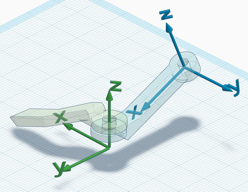
The two examples below illustrate the definition of a joint frame. On the left, the mechanism in the zero configuration with the link frames, and on the right the corresponding joint frame (in red) attached to its predecessor.
First example:
Second example:
There is no need for the origin to coincide with a material point of the link, similarly as for the link frame.
5. Geometrical properties. The relative pose of the red frame with respect to the blue frame is a constant that must be included in the robot model. The previous examples would correspond to something like this:
r_joint TheJoint {
    ref_frame {
        translation = (... , 0.0, ...)  // some translation along X and Z
        rotation    = (0.0, ..., 0.0)   // rotation Y
    }
}
And in the second case:
r_joint TheJoint {
    ref_frame {
        translation = (... , 0.0, ...) // translation X and Z
        rotation    = (0.0, ..., ...)  // rotation Y and Z
    }
}
Where the dots represent a non-zero value. The complete specification of the format for the joint frame is in the next section.
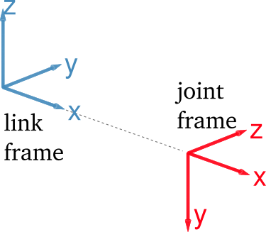
Joint frame format
The ref_frame block within a joint block defines the relative pose of the
joint frame with respect to the predecessor frame (which is a link frame). The
pose is represented with a translation vector and with three Euler angles,
representing three successive, intrinsic rotations about the X, Y and Z axis.
The rotations are applied after the translation.
Distances are in meters, angles in radians.
Intrinsic rotations
The rotation parameters in rotation = (..) are interpreted as successive
rotations about the X, Y and Z axis of the rotating frame. The first number
rx is the amount of rotation about X, the second is the rotation about the Y
axis of the frame rotated by rx, the third is the rotation about the Z
axis of the frame rotated by the previous two rotations. Of course any of these
numbers can be zero. Also, they are interpreted according to the right hand
rule.
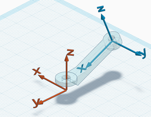
For instance, the frame of the second joint of Fancy (see above) is modeled with this text:
p_joint jB {
    ref_frame {
        translation = (1.0, 0.0, 0.0)
        rotation = (-PI/2.0, 0.0, 0.0)
    }
}
And the frames can be visualized like this:
Discussion
This is an optional section, with more information about the reference frames of the robot model.
Remarks
-
Any link-frame is fixed onto the link, it moves with it, it does not move relative to it.
-
Any joint-frame is fixed onto the predecessor link (which supports the joint), it moves with it, it does not move relative to it.
-
Any joint-frame is fully identified by the successor-frame and the choice of the zero configuration of the mechanism.
-
The Z axis of any joint-frame is the joint axis.
-
Motion of any joint is relative motion between the predecessor and the successor. The relative pose between the joint-frame and the successor-frame (the red and the green frame, in the examples above) is represented by what is commonly referred to as the joint transform.
-
The pose of the base-link-frame is arbitrary. It never appears explicitly in an individual robot model (there would not be any reference to express it, anyway!)
Interplay
After reading the points above a few times and trying the procedure, one eventually realizes the interplay between:
- the choice of the zero configuration
- one degree of freedom in the choice of link-frames
- the joint-frame parameters in the model
I presented the first two points as arbitrary and the third one as a consequence. Of course one is free to revise a choice in order to influence another. For example, given a fixed zero configuration, one might want to change the pose of a link-frame to minimize the number of non-zero values of the geometrical properties.
The degree of freedom in the choice of the link-frame which interplays with the zero configuration differs between prismatic and revolute joints:
- for a prismatic joint it is the position of the origin (translation along the z axis)
- for a revolute joint it is the orientation of the x/y axes (rotation about the z axis)
For example, imagine you followed the entire procedure for the case illustrated above. Now imagine you wish to change the pose of the green frame by rotating it about Z (because you realized it is more convenient for your needs). In this case, keeping the same geometrical parameters in the model would effectively imply a change in the zero configuration.
On the other hand, imagine changing the numbers in the model so as to translate the origin of the joint-frame (in red) along Z. The change has no effect on the zero configuration, but it implies changing the pose of the green frame (relative to the green link - the link itself cannot "translate", because it is assembled and constrained by the joint). In this case the center of mass and the inertia moments of the green link must be changed in the model, to reflect the different pose of the frame.
Finally, changing the geometrical properties so as to rotate the joint frame about Z, implies either changing the zero configuration, or, again, changing the pose of the successor-frame (green).
Why it is sensible
This convention is basically the minimum required to execute numerical kinematics and dynamics algorithms.
If you feel it is overly restrictive or redundant, consider the following arguments:
-
The Kinematics-DSL does not prevent to attach additional frames on each link (each defined with respect to the default link-frame), for whatever use.
-
If one prefers a model without joint-frames, one would anyway need to tell explicitly where the joint axis is, in the body of the predecessor. Locating a line in space requires 4 parameters.
-
The convention requires the full pose of the joint frame, which has 6 degrees of freedom (not 4), but the 2 "redundant" degrees enable to choose the origin and the zero-configuration, independently. DH parameters do not allow that, in general (DH parameters were good in the 70s...)
-
If one wants the default link-frame to be somewhere else than the joint axis, then the joint axis location must be given also with respect to the successor (and not just the predecessor). Furthermore, the kinematic solver working on such a model would end up working with the same frames we described anyway.
In short
The convention for the attachment of frames can be specified succinctly as in
the following:
-
Link frames must be placed so that the z axis lies on the axis of the joint supporting the link.
-
Every joint has its own frame attached to the predecessor. This frame coincides with the frame of the successor when the joint is at the zero configuration.
-
For every link, the relative pose between the supported-joint-frame and its own frame is a constant that must be represented in the robot model.
It is my experience that the simple enumeration of these attachment constraints, although complete, is not very effective to understand what to do when modeling the kinematics of a robot.
Optional frames
More reference frames can be optionally added to any link of the model. Any
frame must be defined with respect to the default frame of the link it is
attached to. The format to specify the relative pose is the same as for the
joint frames. The keyword for the subsection is frames. For example:
link link5 {
    // ...
    inertia_properties { /*...*/ }
    children { /* ... */ }

    frames {
        end_effector { // a custom name
            translation = ( /* ... */ )
            rotation    = ( /* ... */ )
        }
    }
}
Inertia
Any link block must specify the inertia properties of the rigid body: total
mass (Kilograms), position of the center of mass (coordinates in meters),
moments of inertia (Kilograms * meter squared). All the properties must be
expressed in the link-frame.
link link1 {
    // ...
    inertia_properties {
        mass = 1.0
        CoM = (0.5, .0, .0)
        Ix=0.0025  Iy=0.33458  Iz=0.33458  Ixy=0.0  Ixz=0.0  Iyz=0.0
    }
    // ...
}
The example above is a model of a hollow, infinitely thin cylinder of unit length and unit mass, radius equal to 0.05. The link-frame has its origin in the center of one of the bases of the cylinder, with the x axis aligned with the height of the cylinder.
Definitions
Here are the definitions of all the six moments of inertia (discrete case):
$$ I_{x} = \sum_i m_i (y_i^2 + z_i^2) $$ $$ I_{y} = \sum_i m_i (x_i^2 + z_i^2) $$ $$ I_{z} = \sum_i m_i (x_i^2 + y_i^2) $$ $$ I_{xy} = \sum_i m_i x_i y_i $$ $$ I_{xz} = \sum_i m_i x_i z_i $$ $$ I_{yz} = \sum_i m_i y_i z_i $$
Where $m_i$ is the mass of the $i-th$ point of the body, while $x_i$, $y_i$, $z_i$ are its coordinates. The 3 by 3 inertia tensor is defined as follows: $$ I = \left( \begin{array}{ccc} I_{x} & -I_{xy} & -I_{xz} \\ -I_{xy} & I_{y} & -I_{yz} \\ -I_{xz} & -I_{yz} & I_{z} \end{array} \right) $$ The robot model document requires $I_{x}$, $I_{y}$, $I_{z}$, $I_{xy}$, $I_{xz}$, $I_{yz}$, in any order, not the elements of the tensor (note the sign differences). Thus, if you happen to have the inertia tensor of the links (e.g. from the documentation of the robot), then you will have to switch the signs of the off-diagonal elements before filling in the robot model.
Link frame coordinates
As mentioned at the beginning, the position of the center of mass and all the moments of inertia must be expressed with coordinates of the default link frame (see above). The origin of this frame is not, in general, at the center of mass.Numerical properties
RobCoGen distinguishes three classes of numerical properties/descriptors, in a robot model: variables, parameters and constants. Conceptually, the distinction is based on the average changing frequency characteristic of each class: variables change in general continuously, parameters may change, with a lower frequency, constants do not change.3
In any robot model:
- the variables are all and only the joint status variables; the variables are implicit, they do not appear in the robot model
- any numerical property of a robot model can be represented with a parameter
or a constant; this is a modeling choice of the user
- any symbolic identifier (such as
mass_link1) appearing where a numerical property is expected, is considered a parameter - all float literals (e.g.
1.5) and expressions involving PI (e.g.PI/2.0) are considered constants
- any symbolic identifier (such as
For example:
// [..]

p_joint jB {
    ref_frame {
        translation = (1.0, 0.0, 0.0)      // constant
        rotation    = (-PI/2.0, 0.0, 0.0)  // constant
    }
}
r_joint jC {
    ref_frame {
        translation = (0.0, 0.0, jC_tz)  // parameter
        rotation = (0.0, 0.0, 0.0)
    }
}

// [..]
Parametric models
If any parameter is included in a robot model, the model is said to be parametric. In this case, the model effectively represent a class of mechanisms, defined by topological equivalence.
-
Which is a clue that joint limits do not really belong to the same level of abstraction of the joint constraint. Another clue: basic dynamics solvers do not need joint limits, although they obviously need the joint constraint. ↩
-
Unless otherwise noted, the "pose" of a link-frame really means the pose relative to the physical body of the link. Note how this information is purely symbolic, it cannot be quantified nor it needs to. The frame is "there", fixed somewhere specific on the link. ↩
-
I believe this criteria to be common in engineering and computer science. ↩